15 August 2024

This video, Welcoming Britain’s Newest Steam Locomotive, has just been released.
The wait is almost over before we officially welcome H2 Marsh Atlantic 32424 ‘Beachy Head’, nearing the end of a project over 30 years in the making!
We welcomed the filming team from the Watercress Line Film Unit to the Railway who helped produce this short video, looking around this incredible locomotive.
Don’t miss out and join us in celebrating the launch of ‘Beachy Head’ between 23 August and 1 September at our Railway. This also includes our ‘Brighton Works’ weekend gala from 24 to 26 August.
Book your tickets here for the launch event.
Before then, at 11.45am on Sunday 18 August the formal handover ceremony will take place, as the care of the locomotive passes from the team who have created it to the Railway’s Locomotive Operations Department. It will then haul a celebratory Pullman dining train for those heavily involved over the years with the project, and major financial supporters.
Finally, on 5 October, all other registered supporters of the Atlantic project have been invited for a day for them to travel behind the locomotive.
23 June 2024

Tickets and further details are now available for the Gala Launch of new-built LB&SCR Atlantic locomotive 32424 ‘Beachy Head’. This event runs between 23 August and 1 September.
In addition the Bluebell have announced the first dates when you can travel behind ‘Beachy Head’ on the Bluebell’s Golden Arrow Pullman Dining and Wealden Rambler Afternoon Tea Trains! These tickets are available now so don’t miss out and travel behind ‘Beachy Head’ in style this August!
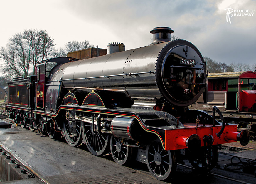
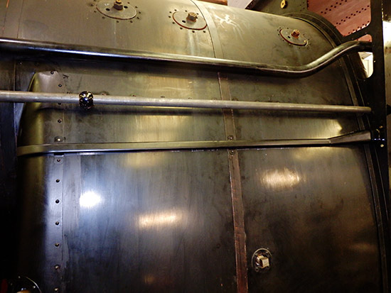
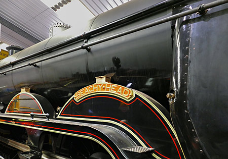
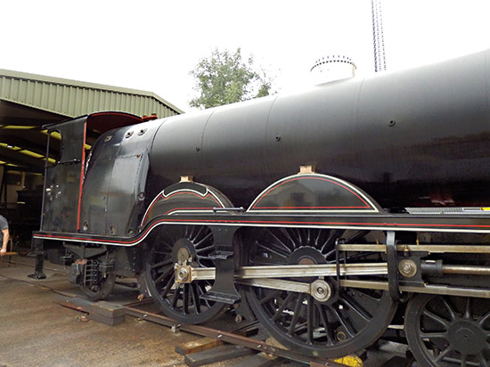
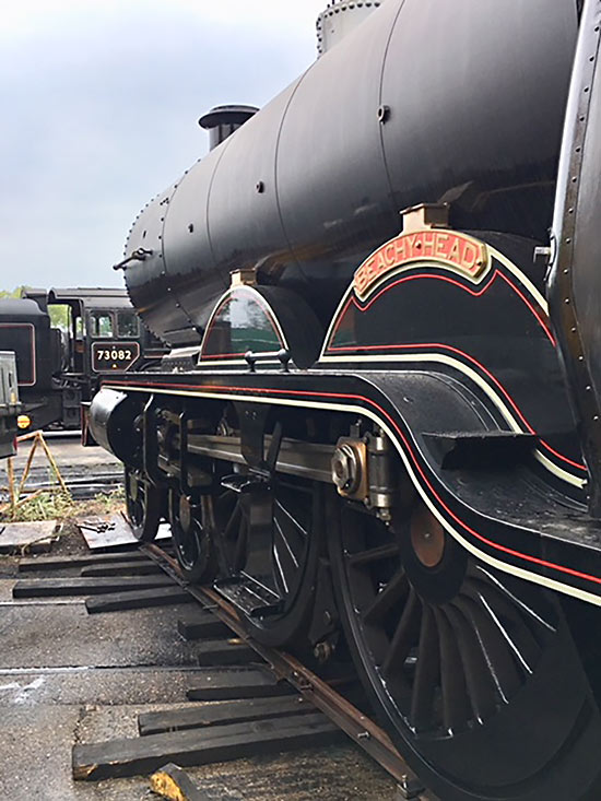
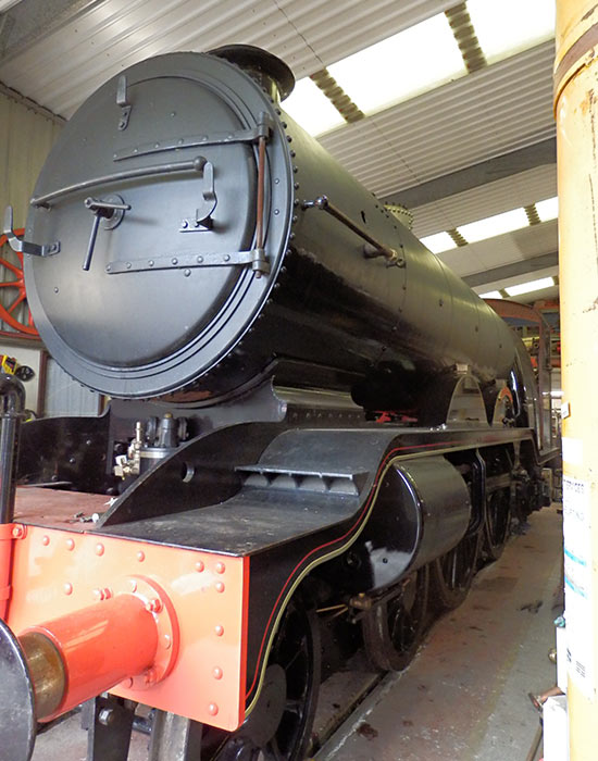
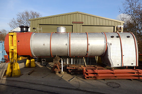
In addition, the Atlantic, with its boiler barrel now having been painted in topcoat and lined, and the whole locomotive having been varnished, will be on display this coming weekend, during the Bluebell’s Model Railway Weekend (29-30 June).
12 June 2024
32424 ‘Beachy Head’ – Coming in August 2024
The Bluebell Railway is proud to announce the highly anticipated launch of the new build LB&SCR Marsh Brighton Atlantic 32424 ‘Beachy Head’. This major milestone in railway preservation will be celebrated with a launch into traffic over the August Bank Holiday, with a launch event running from 23 August to 1 September, marking an extraordinary achievement in railway preservation and engineering.
Tickets and further details will be released imminently so watch this space!
Jack Lamb’s photo below, taken last Friday, shows ‘Beachy Head’ in steam at Sheffield Park.
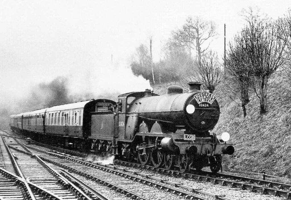
The scale of this achievement, and its importance to the history of the Bluebell line, can be judged from an article covering the potential for rescuing locomotives, and the problem of having to prioritise securing the line on which to accommodate them over spending any money on acquisitions, on Page 7 of the second issue of the BRPS Journal, Bluebell News (December 1959), in it was stated “As each week goes by, more interesting pre-grouping classes become extinct – the loss of the last Brighton Atlantic was an irreparable catastrophe…”.
Of course the locomotive had been scrapped more than 6 months before the Bluebell’s launch meeting in March 1959.
So may I, as editor of this web page, add my personal words of congratulations to the Atlantic team for their dedication in having reversed, in considerable style, that supposed “irreparable catastrophe”.
7 June 2024
32424 ‘Beachy Head’ moves for the first time!

An incredible moment for everyone involved at The Bluebell Railway. Yesterday ‘Beachy Head’ passed its boiler test at Sheffield Park and made its first movements around the yard as seen in this video.
The photo, taken today, shows the loco (which has yet to receive its final paint and lining on the boiler barrel) as it made further tentative test moves around the yard and station, taking water.
Further news will be shared in due course regarding 32424, however further testing is required before the locomotive can enter service.
Congratulations to everyone involved in making this a reality!
A huge thank you to Neil Glaskin for sharing this video and photo with us.
6 March 2024
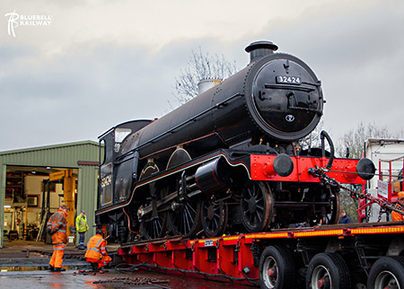
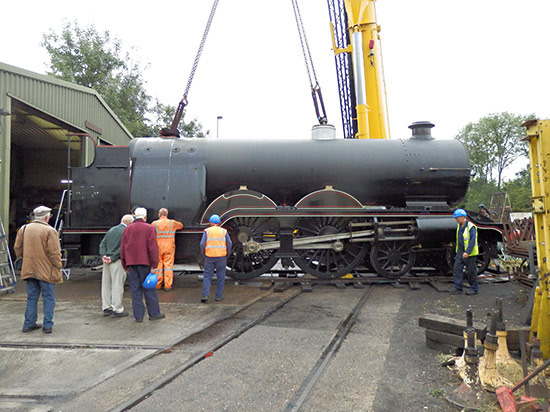
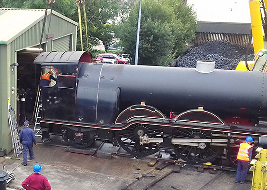
The momentous news and photos here are taken from the Bluebell’s Facebook release. The low loader was used for the manoeuvre since Atlantic House is at right angles to the tracks in the yard. The loco requires completion of painting and lining of the boiler, weighing, boiler test, commissioning, and running in, before a formal launch into service later this year.
‘Beachy Head’ Emerges!
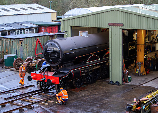
A historic day for everyone at The Bluebell Railway. New build LB&SCR H2 Atlantic No. 32424 ‘Beachy Head’ was transported from its shed at Sheffield Park yesterday afternoon and was partnered with its tender for the very first time this morning.
This is an incredible achievement by the Atlantic House team and everyone involved with this fantastic project. The reality of seeing an LB&SCR Marsh Atlantic is very much reaching the final stages.
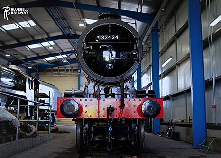
The locomotive has now been moved into the maintenance shed where the commissioning work will now commence to bring ‘Beachy Head’ into service.
Here are a couple of photos of both yesterday and today, showing ‘Beachy Head’ at Sheffield Park.
December 2023
Fred Bailey’s mammoth report covers the whole of 2023 from an engineering perspective. He hopes to have another one available in March.
Work has been progressing well since the boiler was installed in 2022. The work involved is partly trying to join bits at the front to those at the back. Added to this a lot of work has been needed between the frames, in the firebox, in the smokebox, in the cab, it goes on and on. We also now have to finish off all the unfinished work. Making sure valve glands are packed, making sure all boiler fittings are individually numbered and registered in the railways data base. Lots of items have been fitted as a temporary measure. Now they have to be properly checked over and finally fixed into position. Pipes from ¼” to 2″ need to be run, involving careful setting and bending plus silver soldering on some and brazing on others. All the while we do this unexpected problems arise requiring solutions and sometimes some redesign. This all takes a huge amount of time, but we are getting there! Just because an engine looks like one does not mean to say it is finished.
We are approaching the end of the build and have already started the serious business of doing static testing of the dual braking systems. First the vacuum on the tender. And after some funny unexpected items has now proved satisfactory. Next vacuum on the engine. A job in progress. Our vacuum pump whilst of a leading make is not a huge air shifter, so very small leaks prevent us getting the amount of vacuum we require. But step by step it improves. Then air brake systems on tender and engine. We need to get our new compressor running to do those. Our old freebe one dating from the fifties decided to stop working hence a new replacement machine. Our follow on projects will still require compressed air. A lot of final work can not be carried out in Atlantic House so at some point in the first few months of next year the tender and engine will move to the maintenance shed. Obviously the boiler needs a washout plus a final internal inspection. The engine and tender both need to be brought up to running weight and then weighed and springs adjusted accordingly. The engine and tender need coupling together with all hoses in place and further static air and vacuum brake tests done. Eventually the boiler needs to be lit up slowly and all leaks from wherever looked at and cured. More and more and it has not turned a wheel yet!!
I will not proceed further. Needless to say that is just the start of getting a newly built locomotive ready to run on the rails.
Herewith I will start the photographs with explanations. It might be a bumper issue!
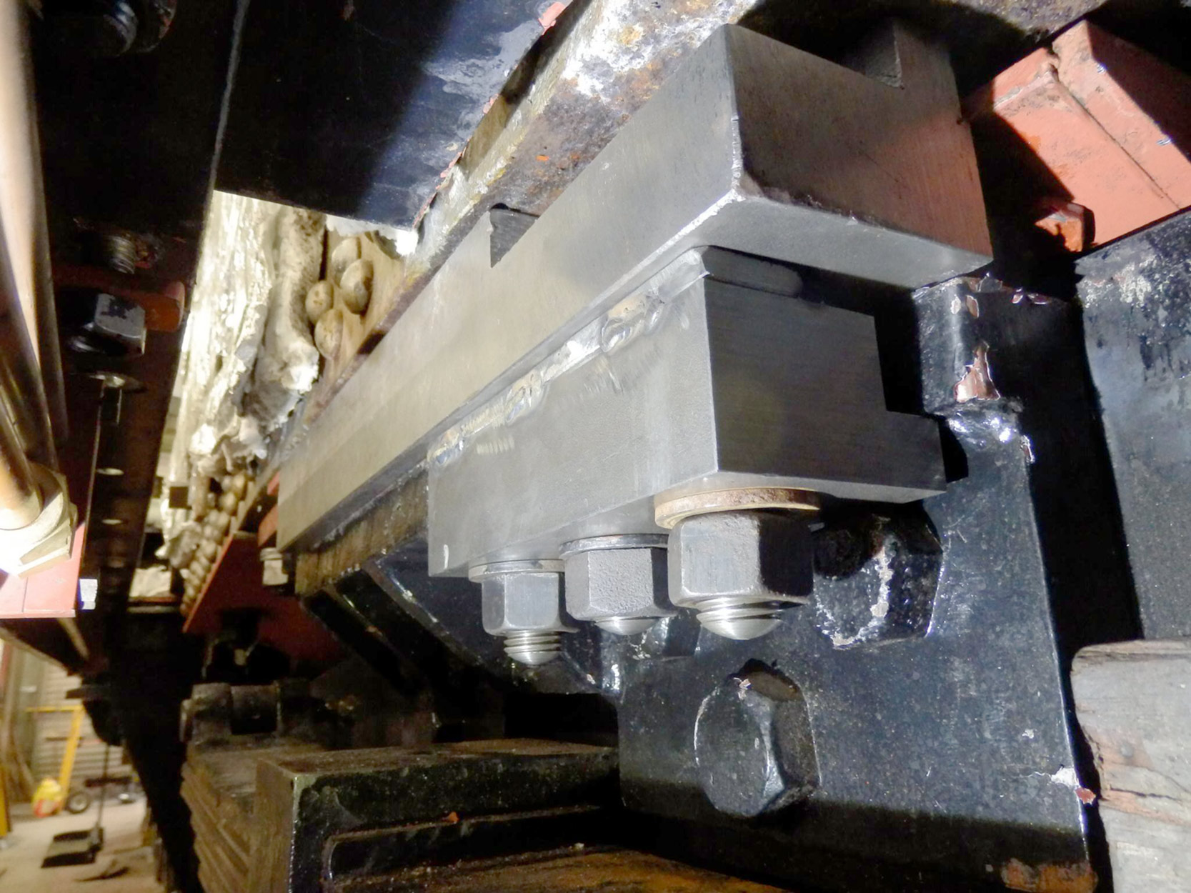
This is the left hand side boiler clamp. The 3 long studs with the nuts one can see are screwed into the foundation ring of the boiler. The big block is a spacer that we needed to adapt the LNER boiler to an LB&SCR chassis. The clip goes over a heavy bracket on the frame and hopefully when the boiler expands and contracts this lot should slide one to the other.
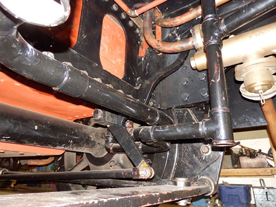
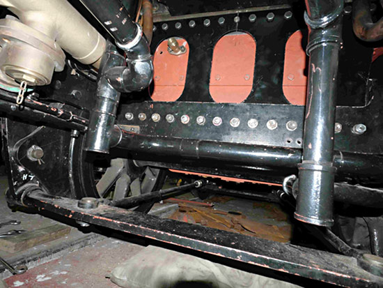
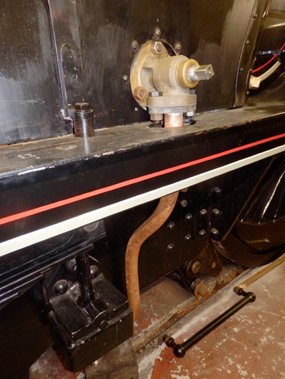
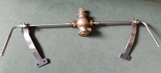
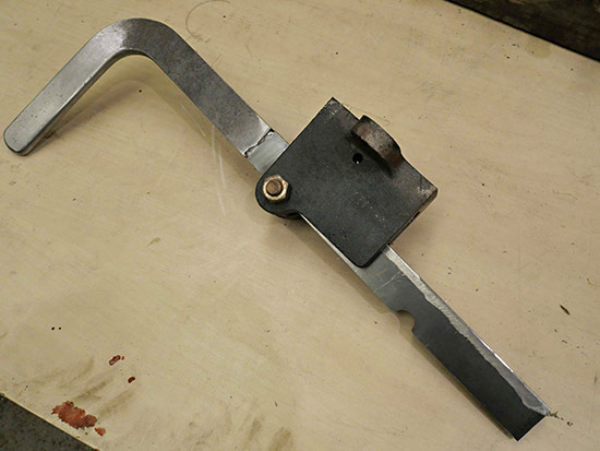
This is part of the nightmare under the cab. Due to our engine having steam heat to the front buffer beam and a vacuum train pipe going the same destination (something the engines did not have when built) we sited the pipes just inside the inner frame on the right hand side alongside the ashpan. Unfortunately that is also where the damper control rod was run. We had to come up with an alternative route and this odd bell crank and the bent arm above are how this has been achieved. If the original drawings are to be believed the front damper did not get much beyond 45° of opening and neither does this.
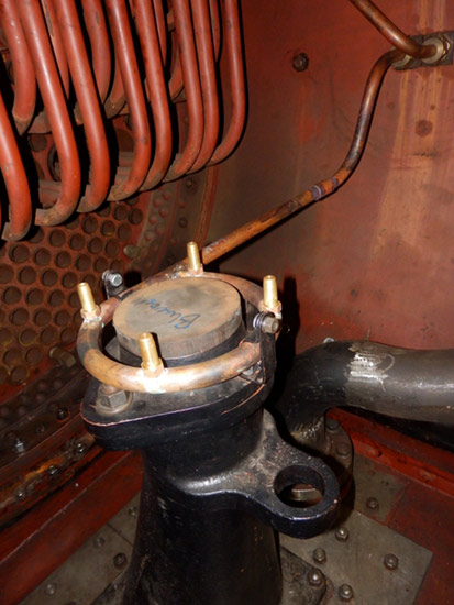
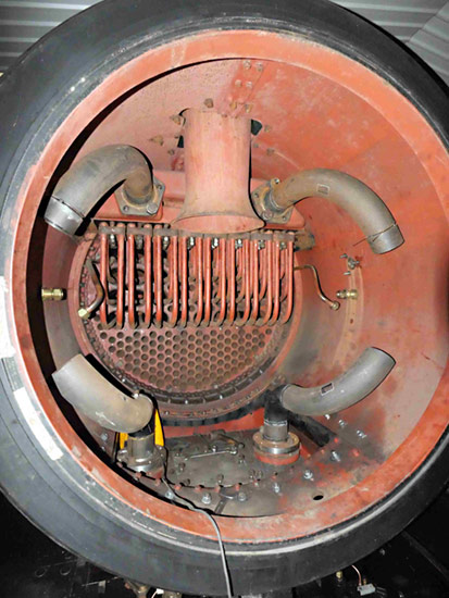
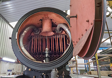
While in the smokebox a blower ring has been mounted on the blast pipe. The big hole in the lug on the front of the blast pipe is to take the exhaust steam pipe from the Westinghouse pump. That and its opposite number, the main steam pipe to that pump, are work in progress at this time. The space allowable for such relatively large copper pipe is somewhat limited both inside and under the smokebox providing some “interesting” practical problems.
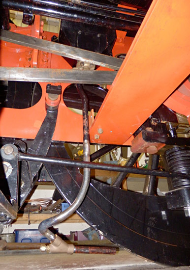
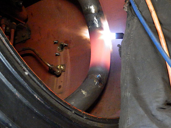
Not every thing happens where it is easy to gain access. Here is one of the four sandpipes that need the steel pipe to be made and fitted partially insitu, but then hot set to obtain a bend then tried again for fit everywhere. Following that the copper steam pipes needed to go through a similar process. Then finally pipe clamps need fabricating and fitting for each of the four. Once one gets to the fourth unit all access from between the wheels is cut off, so the only way in was from behind the smokebox feet first down between the pipes and the valve gear. Oddly once at floor level there is a fair bit of space to work.
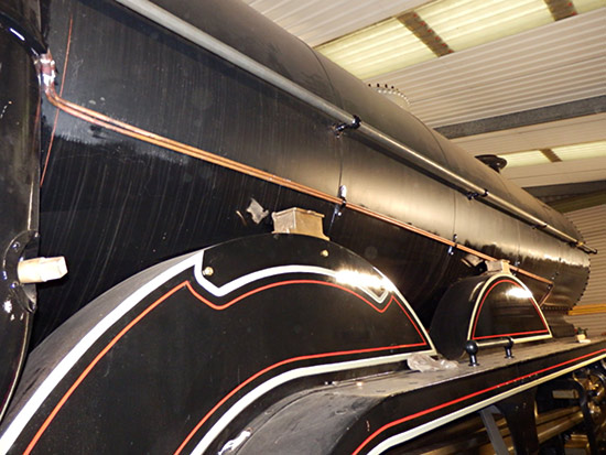
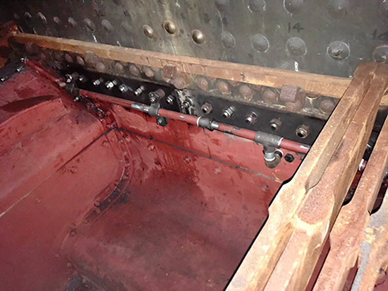
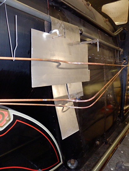
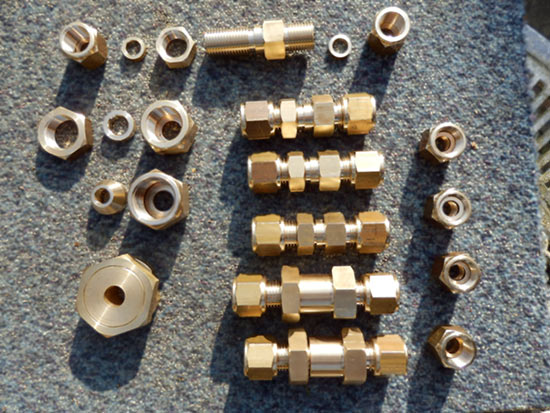
Alongside the boiler, the pipes feeding oil from the Detroit Lubricator fitted in the fireman’s side of the cab. All the clips along the boiler had to be made and fitted then the pipes run and connections made to the front end. At the rear end the pipes have to curve around the throatplate then run through a shroud which expands a little near the cab front where unions in the pipes are located. The pipes along the boiler are silver soldered together as they were too long to run in one length.
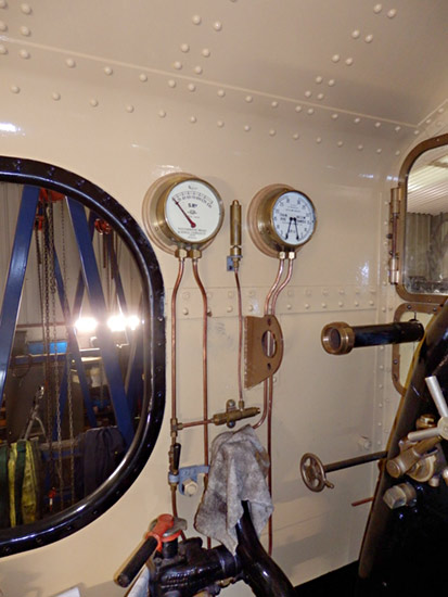
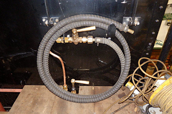
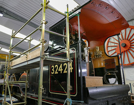
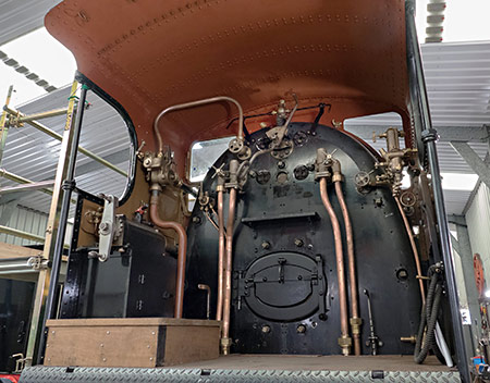
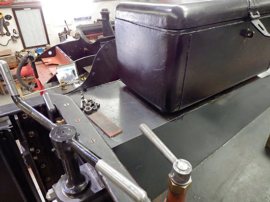
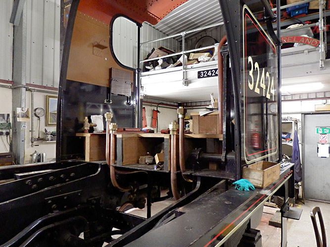
The inside of the cab was stripped of fittings and the backhead given a topcoat of black, and the cab inside a couple of undercoats and a light colour to help reflect light within the cab. In this picture the brake ejector has been removed to enable the smaller piping to be installed together with the cab windows. Much the same is happening on the right hand side of the cab.
October 2023
During the Giants of Steam gala, 13-15 October, Atlantic House will be open, with both a sales stand and the chance to view progress as the locomotive nears completion. With an ice rink occupying the south end of the running shed, access to the yard and Atlantic House will be through a manned gate in the top car park, alongside the Loco Works.
The Bluebell’s Press Release of 6 October confirms that the Atlantic team will next undertake the overhauls of LSWR B4 dock tank No. 96 ‘Normandy’ (with funding available via the Bulleid Society), and LSWR Adams Radial Tank No. 488 (BR 30583) for which the Atlantic group will also undertake the fund raising.
August 2023
During Flying Scotsman’s visit Atlantic House will be open, for viewing only on Wed 23, Sat 26, Sun 27 and Mon 28 August. It will be closed on other days.
The next full opening (viewing and sales) will be for Giants of Steam (Friday 13th to Sunday 15th October).
9 May 2023
- Atlantic House will next be open to the public during the Bluebell on Parade weekend 10-11 June (but NOT on 9th June).
These two days are also the Atlantic Supporters’ Weekend, with the Chairman’s Address and update at 2.30pm on Sunday 11 June followed by the Auction (with viewing earlier that weekend. Items for the auction can be left at Atlantic House on Tuesdays and Thursdays, or by arrangement. There are already some very interesting items donated for the Auction – which will be detailed here nearer the event.The current expectation (and so potentially subject to change) is that the locomotive will be moved out of Atlantic House and into the Loco Maintenance Shed and/or Works to complete painting and commissioning this Autumn, with entry into service sometime before the Autumn of 2024.
The next project for the group will be announced in the next issue of “Atlantic News” which is sent by post to project supporters. It will not be a “new-build”. - John Sandys’ photos above and below show the Atlantic on display at the recent Branch Line Gala.
November 2022
We are pleased to report that every component of the locomotive is now sponsored.
August 2022
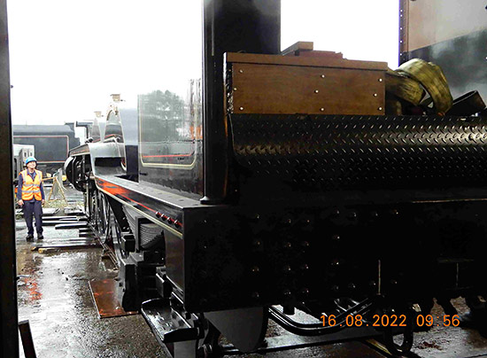
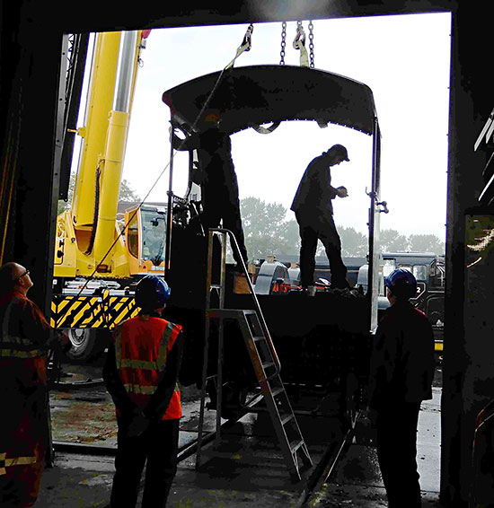
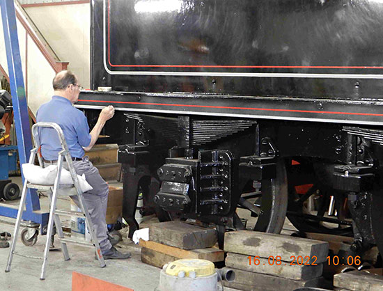
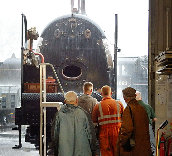
Fred Bailey reports on the long awaited installation of the boiler on to the chassis of Beachy Head (with photos by himself, and others as credited):
Obviously the ashpan has never been fitted to the boiler or the boiler or ashpan been in or on the frames so some issues were expected. We have previously checked as best as we could where problems might arise and taken measures to prevent such things occurring but as with all things it is difficult to plan for the unexpected. One or two items did slip through our previous work in this area and as it happened we were within about 2 inches of the boiler being home and we found a couple of items of concern so the boiler was lifted away and some adjustments made prior to reinstalling, primarily with the boiler clothing and boiler bands.
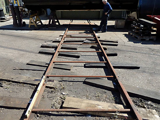
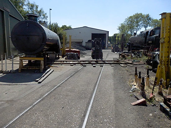
This is the true Bluebell Western Extension, our temporary portable quickly assembled track on which to run the chassis ready for the main job.
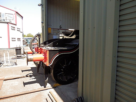
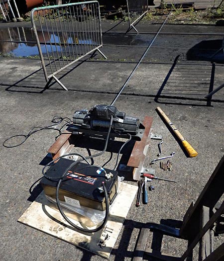
The week before the crane was due we then tried out the winch and Beachy Head’s buffers came out into the sunshine, and for the first time ever looked at the great world outside. I don’t think it was impressed, as soon the loco was back inside. We also had drilled the floor of our workshop in front of our milling machine to take the winch for the reverse manoeuvrer.
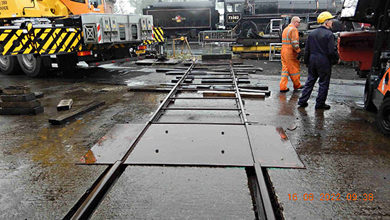
Our track again on the day of the boiler installation.
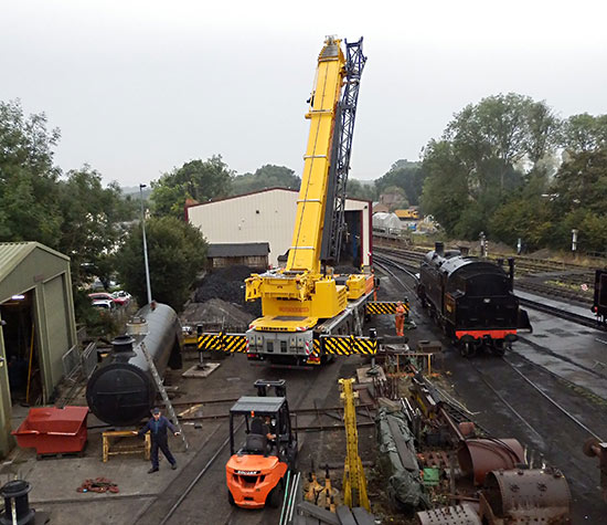
I think our shed is a little like one of those quaint little houses some folks have. If the little old man comes out of one door it will be wet, and if the little old lady comes out of the other it will be dry. Unfortunately BOTH of our doors if opened indicate wet weather. When the tender tank was placed on its frames it poured with rain and now the same for the boiler lift. We did it on the day the weather broke after one of the longest dry spells in history. (Photo: Malcolm Place)
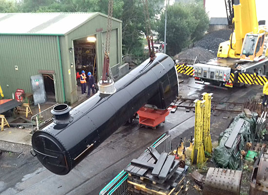
The boiler has been removed from outside of the shed so allowing the temporary track to be assembled and the ashpan is about to be tried onto the foundation ring of the boiler, something we were unable to do until this day. The boiler was not slung level, so it was not possible to fit the ashpan until the boiler slinging was rearranged slightly. (Photo: David Jones)
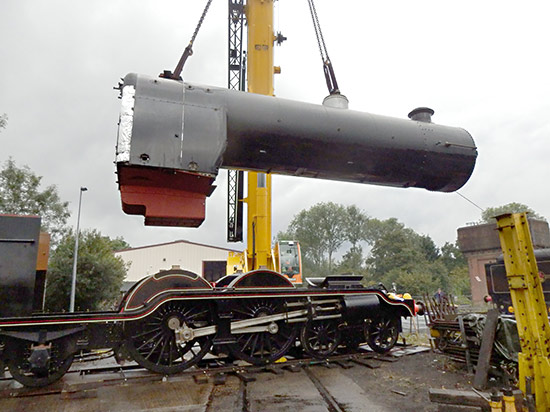
The boiler being guided into position. It is a high lift because the boiler has to be lowered down through the cab front angles. Those angles come within about 1/4″ of the boiler itself, the clothing sheets butting to it on both sides. Also the throatplate clothing actually touches the splashers when the boiler is correctly positioned within the cab front.
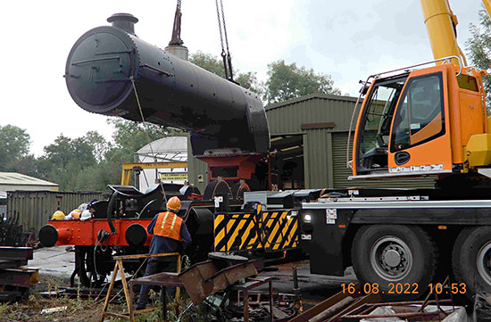
We found some minor points of interference between the ashpan and some other parts and the boiler band joining lugs with a frame stretcher (one we added in to support a vacuum reservoir that were not part of the original builds – change anything at your peril!) The boiler was removed and “adjustments” made prior to its final installation. We also found the boiler was still not level enough so we added a bit of weight to the rear by adding fire-bars to the ashpan. This photo by Malcolm Place shows the boiler being again lowered onto the frames.
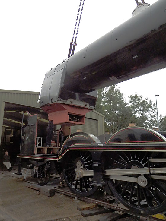
Here we are lowering the boiler for the second time. Half way along the underside of the barrel one might just see a small rectangular gap in the clothing. This is left open as there is another boiler support on the frames that passes up through that gap to help support it part way along. Some fire-bars may be seen in the ashpan.
April 2022
Fred Bailey reports:
I must apologise for not having done an update recently. The problem is we have all been working as usual, but there is virtually no change in the appearance of things. We took the opportunity of lifting the chassis and removing the bogie as we had the slight problem of the ride height of the chassis being about 5/8″ too high. This is not affected by springing or total weight of the engine, so needed looking at sooner rather than later. At the same time, the bogie centre stretcher had been fabricated at the very beginning of the project when funds were very limited. Now while this would have safely served its purpose it would need to be examined on a regular basis in case of flaws developing and under the front of an engine covered in grease oil and dead pheasants it is not a pleasant job to do properly.
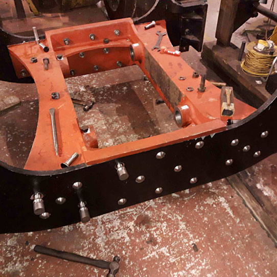
The original engines had a cast steel centre stretcher, so I then redesigned it very closely on the original and we had a pattern made and the unit cast in steel, then machined with full certification. We then drove out the original fitted bolts, removed the fabricated stretcher, then had our volunteer machinist make a new set of bolts which we then used to fit the new cast stretcher. We also managed to correct the ride height problem that as far as we can tell (all of our new parts matching within close limits those on the drawings that we have) may have been due to an error on the original drawings that if corrected was done on the component drawings that now do not exist but not on the bogie assembly drawing that we had for reference.
This photo shows the new stretcher in place, with the last few fitted bolts being tried for fit.
On a similar note we have now lifted the rear end of the chassis (now that the bogie is back under the frames) to address another problem that came to light very near the end of our cataloguing of the Southern Railway and its constituents’ drawings at the National Railway Museum in York. Our chassis was by this time virtually complete, but a later issue of a drawing that we already have seen was discovered that specifically showed a change to the side play on the rear carrying axle on the locomotive. This increased considerably the side play on that axle and it has required us to produce new axlebox guides (or horns if one prefers) as there was insufficient metal in our original castings to modify them without seriously impairing their strength.
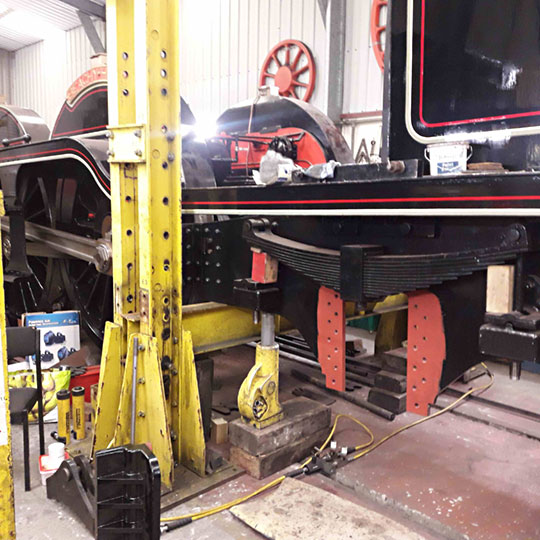
So the old ones were removed and again another set of 36 new fitted bolts made as replacements. As an aside, these bolts are made with a integral chucking piece at the head end with a groove between it and the head proper and a centre in the thread end. The part that fits into the frames being left over size. Once we have the holes made in the horns reamed through to those in the frames then we then make up step gauges with diameters going up in half or one thousandth of an inch intervals. Using these we can judge the size of each hole and if there are any variations these can be reflected on the bolts themselves, each one being skimmed down in the lathe to fit tightly in each hole. After trial in its hole then the chucking piece is removed and the shape of the head finished. Each bolt is then driven in and the spring washer and nut fitted, being fully tightened once all the bolts are in.
On the left we see the back of the chassis sitting on one of our lifting frames with the old horns removed. and a new one ready to try in place.
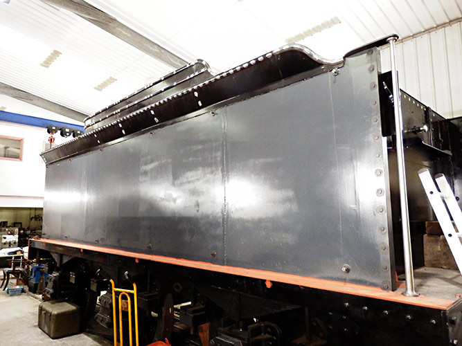
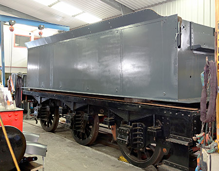
The tender is finished other than a final rub down, a final top coat of gloss, the lining and transfers and then varnish to complete.
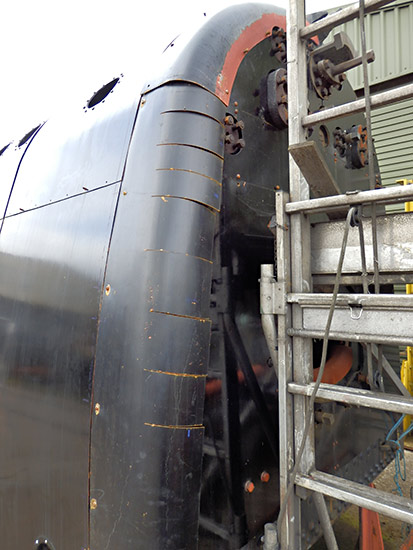
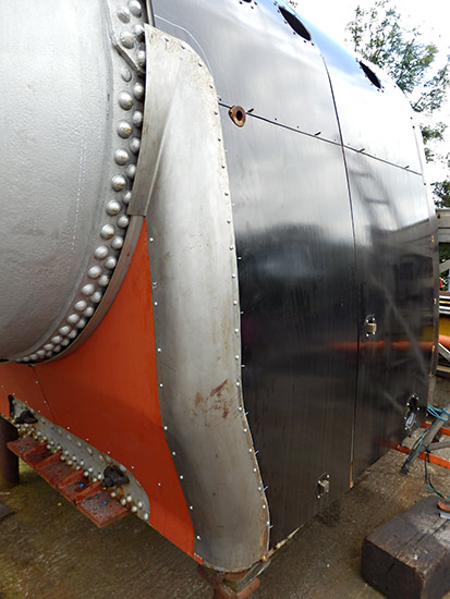
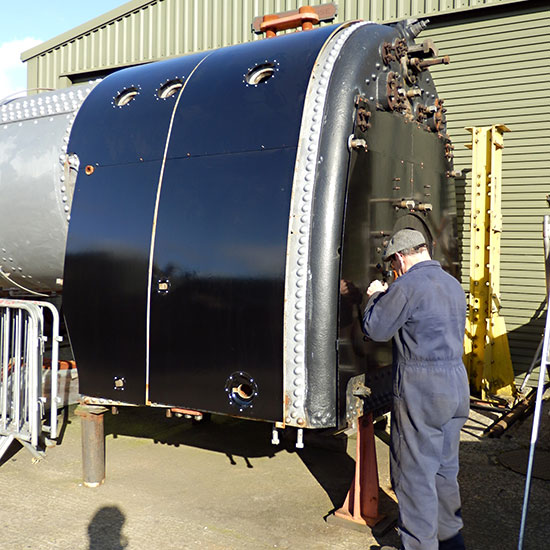
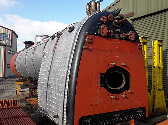
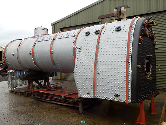
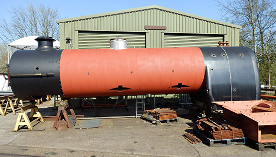 The boiler clothing has taken a long time to get satisfactory but once all was fitted we decided that access to it once in the frames would be impossible hence the boiler had all of the sheets removed and all the insulation applied then the sheets refitted including the smaller belly plates and the boiler bands fitted. This decision came about by a change we have decided on in the lifting of the boiler. Normally a wide strop is located just near the throatplate and another somewhere on the barrel close to the dome. This of course is not possible with all the insulation and clothing in place. Our plan to do the boiler lift in our main works proved not to be possible due to there being insufficient height under the gantries to lift the boiler into the frames. We are going to lift from two special attachments, one on the two safety valve pads and one on the dome opening. The latter one of these is being made at this time. We hope to fit the boiler shortly during the summer.
The photo on the right shows the boiler insulated and with its clothing sheets now fully fitted.
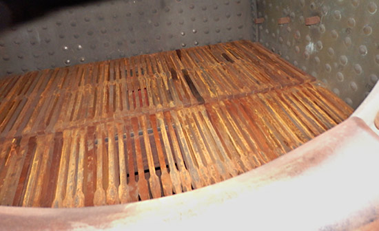
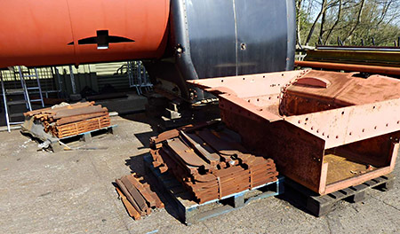
The first photo below shows the ashpan (requiring a clean and repaint, having been stored out of doors) and the grate bars on pallets. All of these are needed to complete the grate.
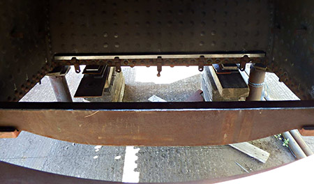
The last photo for this report shows the centre grate support, weighing 350 pounds (159Kg for those fully metricated) in position ready to take the bars, which will only be fitted once the boiler is in place.
July 2021
We are pleased to say that a large number of components for the locomotive have been sponsored in the last two months, and so currently there is a very much reduced component sponsorship list.
Fred Bailey reports that work has been proceeding steadily on the Atlantic although still slower than one might wish due to the limitations imposed by the covid situation and also due to the weather.
The boiler is outside of Atlantic House but we need to spend a lot of time out there working on the boiler clothing sheets. We have all been involved with these parts on other engines at the railway and they are notorious for being (shall I say) “difficult”. If all of the parts already exist and they have been removed to allow work to be done on the boiler they never seem to go back in the place they have come from. Often new fixing holes have to be drilled in old sheets. From a distance they look lovely, but look closely and you will undoubtedly see the results of many hours of angst and frustration these parts have given fitters for many years. I am told that when our 9F was put into working condition all new boiler clothing was required then and some of the parts were made by skilled outside industry to the original drawings and almost none of it fitted. Quite major surgery being required to get it to fit properly. (What a shame and what an expense this will entail as a lot of that work will need to be done again due to our out of service locos being stored outside).
On a happier note, work on the tender has progressed very well and mechanically it is now virtually complete. Obviously all the braking systems will need to be checked to make sure they function as they should and all parts checked for proper assembly and that all the relevant means of retention of fasteners are in place and properly applied. The double skin is fitted now over the tank itself and it certainly improves the appearance of the tender. This is all now being painted and as I write this the first topcoat is about to be applied to the tank itself. A lot of the other parts are already top-coated such as the upper works, toolboxes and coal raves.
So from here we will proceed with the pictorial record of our endeavours.
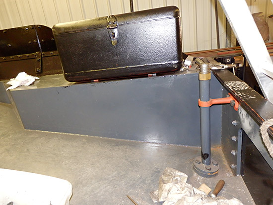
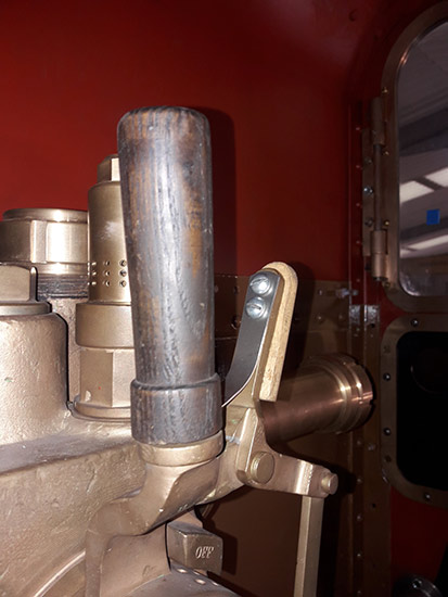
This is the fireman’s side of the tender and shows the LSWR type toolbox as fitted in BR days together with the handbrake handle. Just behind that near the side of the tender is the top of the tender water level gauge and to the right is the handle for the injector water valve.
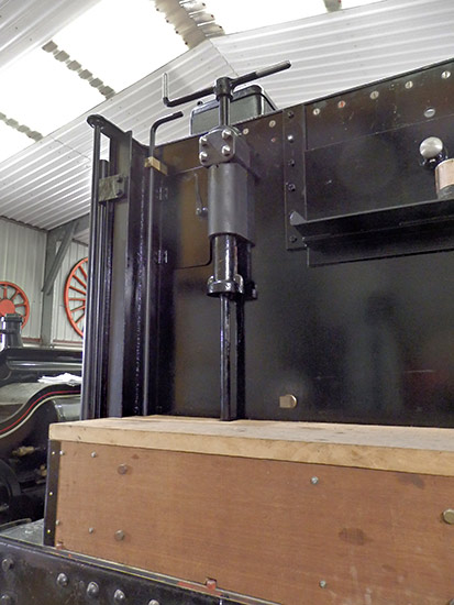
The tender front, showing the typical “Brighton” handbrake arrangement. The key through the slot allows the air brake to be applied whilst the handbrake is wound off. The lower rod moving up and down freely in response to the application of the air brake. (This in turn actuated by the application of the vacuum brake when working a train).
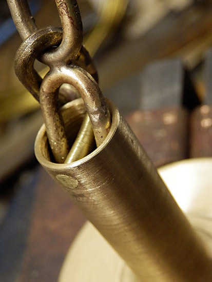
To the left of the handbrake is tender water level gauge. By turning the crooked top of the tube clockwise 90° a plug cock near the bottom of the tank is opened allowing water up inside the tube of which the handle is part and the level of water is indicated by it running out of hole drilled at intervals in the side (when open) of the tube.
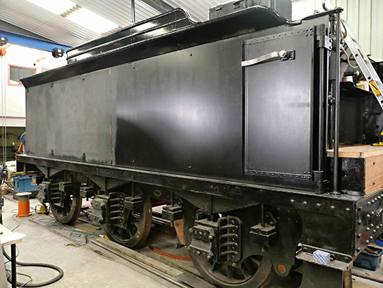
This photograph shows the tender side with the undercoat in the process of being thoroughly flatted down ready for its first top coat. One can see how nice the double skin makes the sides look.
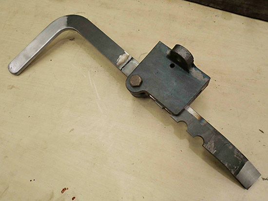
Also in view is the tender door in the open position. The long arm swings through just over 90° and in the position shown would be with the door closed and the arm on the inside of the cab handrail.
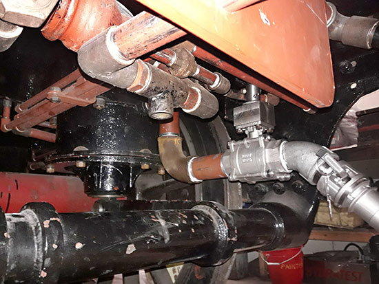
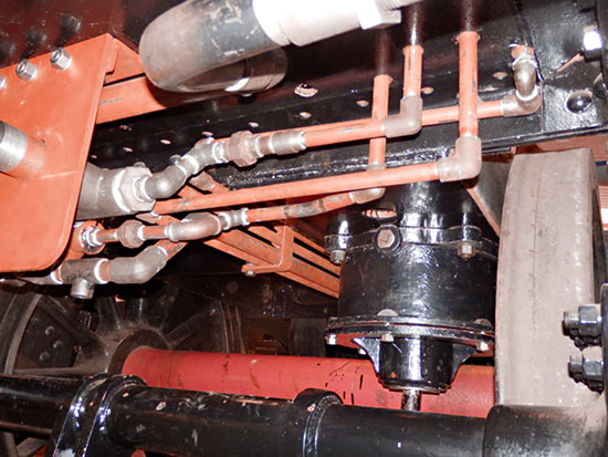
Here we are under the front of the tender. Most of the smaller pipe work is all involved with the braking systems. The silver valve is the driver’s side injector water valve with an adaptor above to make a secure connection to the operating rod from the handle. The black cylinder to the left of centre is the air brake cylinder for the tender.
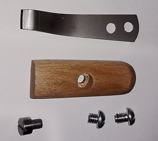
It is not all large items either. At these later stages in construction there are miriads of smaller details that are needed. All take time almost out of proportion to their size but each piece has its part to play on the finished locomotive. A lot of these were jobs from my own workshop where I carried on although vulnerable to this covid thing but allowed to work from home.
Here they are fitted. The odd screw fixes the wood to the bronze handle.
– x –
Now on to the bane of our lives, the boiler clothing. At present, weather permitting we are concentrating on the firebox end of the boiler where a lot of the more tricky work has to be carried out. The backhead area has been in place for quite some time now, but with covid and weather it is only recently we have returned to this area. You may remember that we had a lot of the difficult sheet metal forming done professionally and this has saved us a lot of work as this class of work is outside our expertise, however we still have to make it fit. I touched on this in my introduction to this update re the 9F.
Experience dictates that it is difficult to get items made to drawings with all cut outs etc. already in place so it just bolts together. Folk who have never removed their nose from the computer screen and ventured outside the office into the real world of one off builds may think stuff fits straight off the file. Well yes it does happen, but where one cannot tie things down to close tolerances then hand fitting has to take place. I have copies of the firebox drawing for the Ivatt Atlantics, but ours differs in a lot of areas from that ideal. So we cut the parts to fit what we have.
We thought that the “simpler” shapes around the periphery of the backhead would be the easiest to fit, but unfortunately these have proved to quite difficult and in fact some of the parts have needed to be cut so that the radius to match the boiler can be adjusted. It looks horrible to start with but once all welded back up and ground off flush they will look fine. It takes a lot of skill, patience and dogged determination to do these jobs.
An unfair picture showing the cuts required to allow the shape to be manipulated to fit to the rest of the clothing and crinolines. Once satisfied with the fit then the slots will be tack welded in places while it is in position, the final seam welds done on the bench later.
After all of this we still need to locate the positions of the washout plugs then cut out the plate to match the escutcheon that protects the hole edges and helps stop the insulation from escaping. Those parts then need fitting in position.
This is the similar part that covers the front corners of the firebox. We needed to cut 2″ off of the back edge of both of these pieces as the forming company had left them over-size but oddly after that bearing in mind the awkward shape they fitted reasonably well. A sore arm and wrist from pistol drilling and then tapping all of the screw holes was a small price to pay for the result. But again we still need to cut holes for the washout plugs and their surrounds.
This shows a pocket on the inside of one of the boiler barrel clothing sheets that allows the top of the driving wheel splasher to pierce the boiler clothing. This one is more complex than the other pair as it spans across two boiler clothing courses.
I think that is enough for now, but with luck progress is still being made and we hope to do further updates later.
December 2020
The component sponsorship list has been updated.
Fred Bailey provided this update two months ago, so my huge apologies to him, the project team and supporters, for the delay in providing it to you, which is entirely to be laid at my door.
1st November 2020
I am writing this just as we are about to enter another period of lock down and as yet I am not sure of its implications to our project, but rest assured once we are able we will be pushing forward with the construction of Beachy Head.
At the beginning of September, Atlantic staff who are trust funded were allowed back to work under strict conditions due to the Covid 19 pandemic. Our shed is basically a pod on its own and we all are (or at least members of our families are) in the vulnerable category so we have throughout been extra careful regarding hygiene and distancing and this obviously continues. We under no circumstances are allowed visitors to Atlantic Shed unless we have prior knowledge and there is good reason to visit. To look around is not one of those reasons.
Unfortunately due to lockdown from the end of March to the beginning of September with all the lovely weather we had we were unable to maximise our progress on the boiler lagging and clothing as planned.
The result is that although any finish date has been severely set back we have managed to make some progress up until now.
Although the background is rather cluttered the steam feed, delivery and (unseen here) overflow pipes have been made up and fitted to the injectors.
The remaining sections going to the combined injector steam and non return valves on the backhead will have to wait until the boiler is installed.
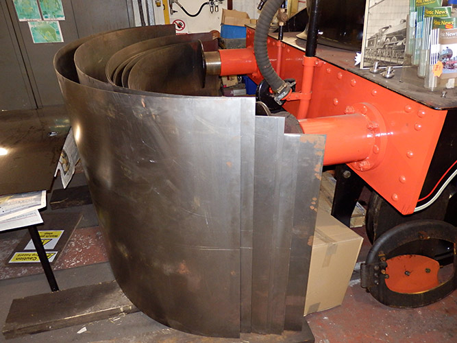
Here are the basic boiler clothing sheets as delivered having been laser cut and rolled.
Each has about 8” of excess material on each end that we need to remove. This is needed to allow the radius of the rolled sheet to extend fully to the ends. These look thin but it takes three people to move each one, they being rather unwieldy as well as surprisingly heavy. A lot of careful work will be needed on these to get them to fit accurately to our boiler with cut outs for hand rail knobs and splashers etc needed. One of these latter cut outs actual straddles the joint between two sheets and has a boiler band running over it.
The firebox clothing sheets have sufficient paint on them now to allow them to be placed in position on the boiler primarily to allow us some more room in the shed so that we can do further work on the barrel clothing and now as well the tender clothing. All the insulation material to wrap the boiler is in stock and is now being stored in the tender coal space.
Work is starting on the corner sheets that bridge the gap between the firebox sides and the backhead and also the firebox sides to the throatplate. The work involved in these parts seems never ending. It is difficult to work with and has to be right as it is blatantly on show for all to see.
All of the coal rails and their infill pieces plus the beading around the top edge is now all fixed and the heads of the fastenings (seen above as silver spots) will be painted shortly, but we are going to purchase the first two of the tender clothing sheets and work on them riveting various pieces to them before fitting them. Only then will we obtain the next two sheets.
Again handling is a problem as each plate is 10 feet 6 inches long, 4 feet 6 inches high and 3mm thick, each weighing about 200 lbs (100 kilos for the younger folks). The front handrails are fitted and work is now taking place on the cab doors and the toolboxes.
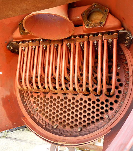
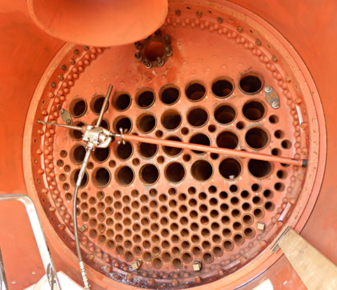
We have now managed to install all the superheater elements into the boiler so moving forward yet again. Fortunately we have a range of work open to us to cater for the vagaries of the weather.
I am not sure when our next update will be but rest assured we are still here and will when possible be working towards the completion of this wonderful project of ours.
March 2020
Fred Bailey provides an update on recent activities on the Atlantic.
As we are in effect all under a form of house arrest at present this has proved an ideal opportunity to update you all on Atlantic progress.
The main work this winter was meant to be completing and fitting the boiler clothing sheets that protect and keep the insulating material in place now that the boiler itself has passed its hydraulic test. Unfortunately however, the winter having been so wet we have been unable to do anywhere near as much as we would have liked of this work. The boiler being outside does not help as these sheets need frequent trips to the boiler to check for their fit especially where holes need cutting to clear all the various parts that protrude through them. In the case of the firebox, these are mostly washout plugs and washout doors. In the main the backhead clothing is complete as are the sheets covering the firebox, but we still need to fit the curved sheets that go between the backhead and the firebox top and sides. The sheets for the boiler barrel are on order but are now likely to be delayed by the flu virus pandemic. Likewise all work on site has had to stop for the same reason.
The tender being inside has progressed fairly well helped a lot by our now having a new member to our team now retired and looking for work on a real engine rather than those of Maunsel’s design! So welcome to the team Melvyn Frohnsdorff.
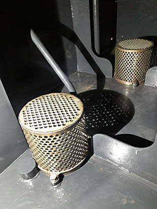
| Left: Starting inside the tender I have now crawled down inside to the front of the tank and fitted the two stainless steel strainers fitted over the two holes for the injector water feeds. All parts laser cut by MLFabcuts and TIG welded by Henry Mowforth.
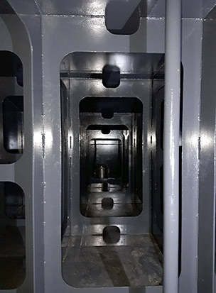
Right: Fortunately, when I designed the baffles and the internal supports I left a clear way through the centre to get as easy an access possible to the front end. |
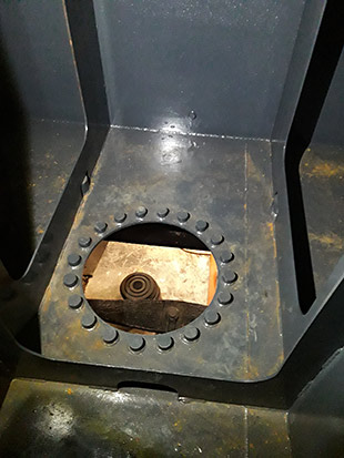
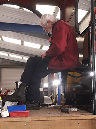
| Left: Also at the stage of drawing up the tank I added a feature not present on the originals. A manhole in the bottom to allow those of us of a slightly fuller figure and in advancing years to allow access to the inside. The tank filler is an oval 14″ x 10″. Hands up those that could not only drop through that hole, but be able to climb out afterwards!Right: At long last we have got around to finally assembling and fitting the fireman’s seat in the cab. Dave is quite satisfied it is strong enough as he is seen trying it out whilst doing some intricate fitting to one of its parts. The drivers incidentally did not get a seat from what I have seen, although the original drawings show one on the tender front right behind the reverser. I imagine they may have been removed as they must have made access rather difficult. |
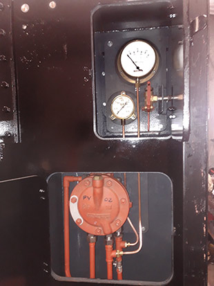
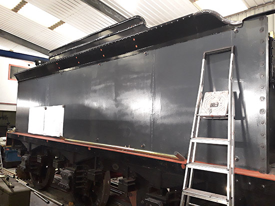
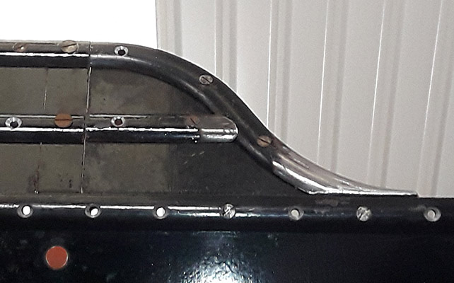
Below: In lieu of a seat we have added two cupboards behind the driver. The lower one contains the vacuum air proportional valve for the braking on the tender and the upper one contains a vacuum reservoir gauge and an air reservoir gauge, together with the vacuum release valve. The gauges are there primarily for fault finding purposes. The glare in the picture comes from the new LED type tube lighting. (Note to self “Must remember to turn them off before taking photos in future”).Next we see the tender beading that goes all around the flared top of the tender and the start of work on the coal rails and coal retention plates. (On the original Atlantics these latter items were added in Southern times).
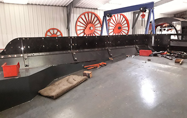
| This is an inside view of the same. All fastening shown are temporary. |
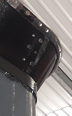
Below: The next 3 photos are of Keith’s handiwork “hot setting” the D shaped steel used for the beading and the coal rails. This first being the front of the coal rails where they dip down to the tank top.Where the beading goes around the rear corner of the tender tank. An awkward shape to achieve. In effect a 90° bend, but with the top edge at an angle of 60° to the bottom edge.
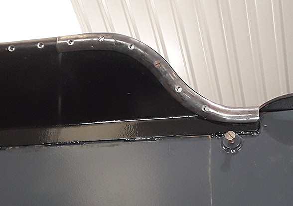
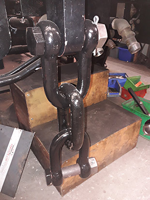
This third photo shows where the beading then drops through a reverse curve from the top of the rave down to the tank top. The bottom part of it has to then be pulled out by about 30° so that it will lay flat on the outside cladding sheet (which is yet to be fitted) all the while being in contact with the flared tender top.Finally we have one of the pair of safety links that go between the engine and tender either side of the main draw-bar. The shackle hanging at the bottom is the one that will be attached to the tender.
October 2019
A very happy Fred Bailey provides the following update!
Well a major milestone has been reached with our Atlantic project, and I must admit we are all relieved and excited by the prospect of our target of finishing the engine, being now one major step forward. Sorry to say it will not be running soon, but our unofficial target of Summer 2021 is possibly fairly realistic given no major un-forseen circumstances getting in our way.
YES, THE BOILER HAS NOW PASSED ITS HYDRAULIC TEST.
After a lot of work over the past few years on Tuesday 29 October the boiler was given its hydraulic test, witnessed by the Boiler Inspector. We have spent quite some time working towards this day and fortunately the day was dry (so that any leakage may be seen) and not too cold. The test pressure was raised by use of the main works’ pneumatic water accumulator pump and once at the test pressure the pump was stopped.
In an hour or so the small insignificant weeps here and there (that will almost certainly take up when hot and the metal has expanded) made virtually no discernible indicated difference in pressure on the test gauge. Work can now continue on the boiler clothing, something that will take quite a lot of time especially if we get a hard winter. We do have a whole raft of work indoors too on the tender.
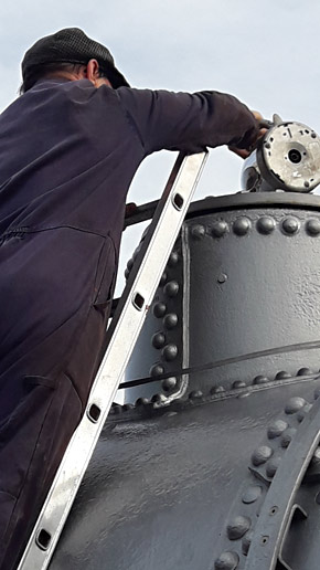
The photo on the right… Obviously before testing the boiler has to be completely full of water with all high spots bled of air, however our shed is some way from any water supply so we had to do the best we could. Here is Tony filling the boiler. It took quite some time!
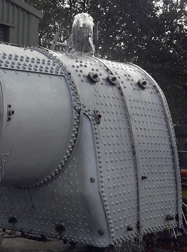
| Mind you he could pour quite quickly – you can see here the water coming out of the safety valves which were released in order to get the air out. Seriously we used a large hose from right across the loco yard that is fed from the water tower to fill the boiler. It filled quicker than we expected hence the overflow seen here.When taking the hose out of the boiler it looses some water, so the previous picture shows the dome being topped off before putting in the plug. The safety valves were filled in the same manner.
The reason that the safety valves do not work on the test is that we have a special clearly marked set of safety links that are short enough to gag the valves. They will be changed before the valves are assembled properly with their springs. |
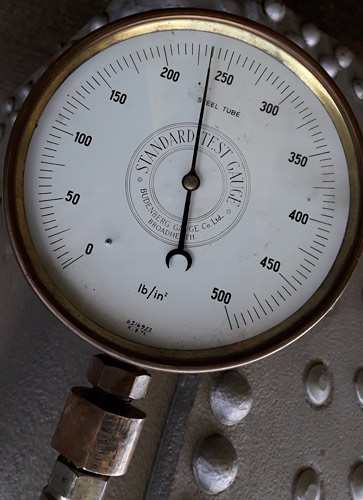
Right: The test gauge on the boiler sitting at the test pressure, with the pump disconnected.
– x –
In Atlantic House the tender tank has been lowered on to the chassis and is in the process of being bolted down. We had another little success here too. We fitted the 26 one-inch Whitworth studs into the bushes welded into the tender base by the tank fabricators in Gloucester, and they all went through the holes in the chassis with no problems or damaged threads. Not bad considering there was only about 1/8″ clearance in the holes for the studs, the holes possibly having been there since 1901 or so.Work is continuing on the boiler cleading sheets and tender at the same time. The boiler cleading progress could possibly be hampered by adverse weather the boiler being outside, but the tender ensures that plenty of indoor work is available.
– x –
Matthew Cousins’ photo below shows the new tender body as initially sitting spaced off its modified ex-LBSCR chassis, soon after it was moved into Atlantic House back in August. The all-welded tank is painted inside and out with 2-pack epoxy paint, but this will be concealed by the riveted external cladding.
July 2019
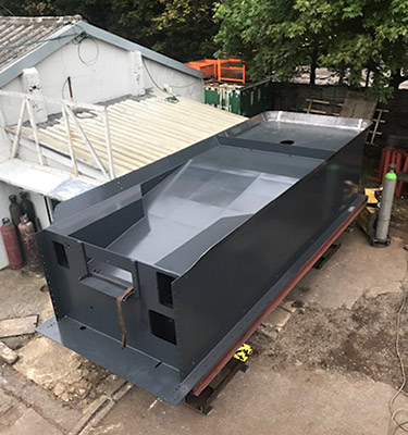
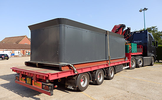
A short update on the Atlantic’s tender tank, which was delivered to us on Wednesday 24 July. It still has to have an outer skin fitted around it, and all the coal rails, cab doors, etc, added.We start with a couple of earlier photos, kindly provided by D G Welding, showing more of the construction details.
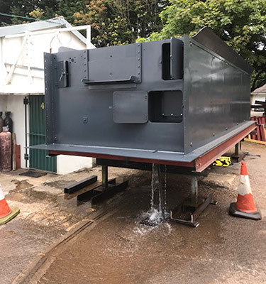
| This is a view of the front and top of the tank, close to being finished, outside at D G Welding’s premises. | The tender front with the various equipment doors added. The tank had been filled with water to ensure it was water tight, and the photo shows the water draining out afterwards. |
| The tank arriving at Sheffield Park early on 24 July (Fred Bailey) |
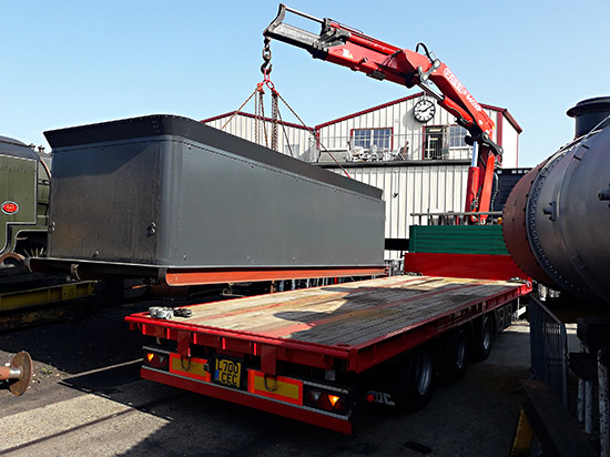
| The tank about to be placed on the ground opposite Atlantic House. The skids under the tank are temporary and will be removed at the time the tank is placed on the tender chassis. Our boiler is just seen to the right. (Fred Bailey) |
Once we have completed some more work in Atlantic House, the boiler will be moved out of the way, and the temporary track laid to enable the tender chassis to be brought out of our shed so that the tank can be placed on the chassis. After pushing the tender back into the works, our temporary track will be lifted and the boiler returned to its spot ready for its hydraulic and steam tests.We are still progressing with fitting the boiler clothing sheets at present which is always a long and taxing job to do neatly. They will of course be removed for the tests to be carried out, but hopefully the time spent now will be saved off of a running test certificate later.
June 2019
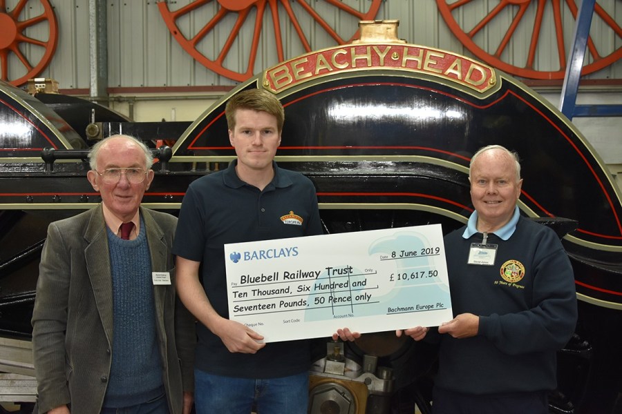 Bachmann’s website carries a report on the presentation of this cheque to help complete our H2 Atlantic ‘Beachy Head’. Do also watch this video on that page too.
On Saturday 8th June 2019, Bachmann Europe Plc visited the Bluebell Railway during its Atlantic House Open Weekend to present a cheque for £10,617.50 to the Bluebell Railway Atlantic Group. Following the release of the acclaimed Bachmann Branchline OO scale model of the H2 Class Atlantic locomotive in 2018, the donation was made in recognition of the assistance provided by the group during the development of the Branchline model.
Richard Proudman from Bachmann Europe presents the cheque to Atlantic Project Chairman, Terry Cole (left) and Secretary, David Jones (right).
An update on progress, thanks again to Fred Bailey. The photos of the tender tank construction have all come courtesy of D G Welding in Gloucester, who are making a good job of this work, and it is likely to be delivered earlier than initially expected.
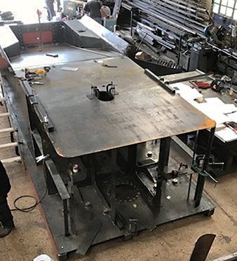
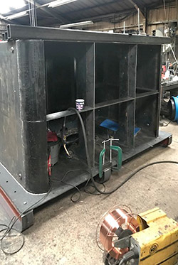
The most major work at present is indeed the construction of the tender tank. Once the basic shell is finished it will be shipped to the railway for us to complete. A large amount of work will be involved here, as the tender tank has to have another skin fitted around it, and all the coal rails, cab doors and a myriad of other features need making and fitting. We start with pictures of progress on the tender tank.
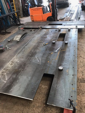
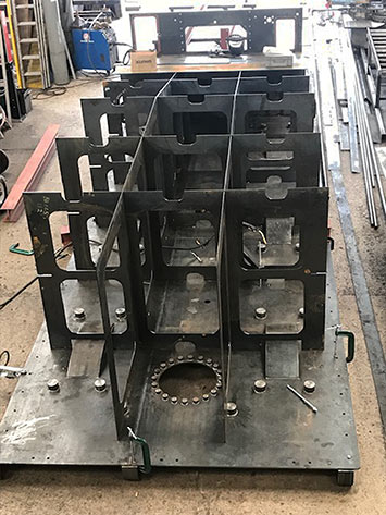
| This was taken in early May and shows the first stage of the tender tank construction, with the baseplate taking shape with one of the internal splashers to clear the wheels visible on the left. These cover the rectangular cut outs in the baseplate. The round bosses are threaded internally on the underside to take the studs that hold the tank down to the chassis.Photo courtesy of D G Welding. | Here is a view of the tender taken from the rear looking forward showing the baffles used internally to support the sides and the top. The inner tank is all welded where the originals were all riveted, with T shaped steel taking the same positions as the plate baffles in the welded version.Photo courtesy of D G Welding. |
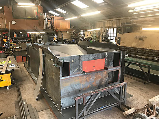
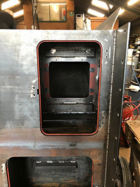
| Left: The tender tank seen from the cab end. The 3 smaller cut outs are to be fitted later with doors. Those on the left or driver’s side will contain a vacuum air proportional valve in the lower cabinet and two gauges and the vacuum release valve in the upper one. On the fireman’s side the single door is alongside the handbrake and is primarily for access to the underside of the later toolboxes and also to allow a 6 foot long container for sandwiches, rain coats or whatever. Or maybe a spare shovel or two!Photo courtesy of D G Welding. |
Three final photos for now of the tender tank, courtesy of D G Welding:
| A closer view of the driver’s side cabinets, with angles ready for mounting the backplates carrying the proportional valves and gauges. |
Two views of the tender body from the rear, as of 17th and 19th June. |
| Moving on now to progress “in house”, the lagging of the backhead has been completed but some has now been removed for access to stay heads etc. in case of problems under pressure test. It is likely some may leak a little and will need a bit of TLC administering to them.This photo shows the lower portion of the backhead lagging in position. The upper parts have also been carefully made and fitted but are now removed. |
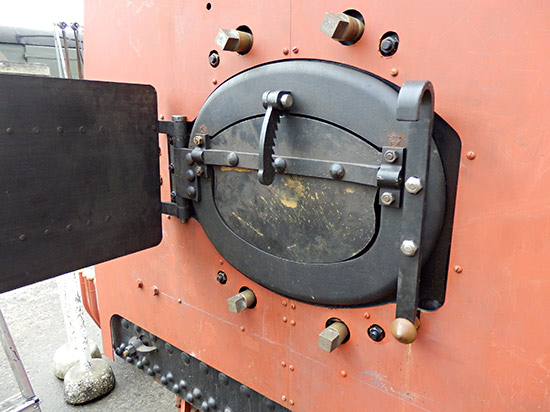
| The same lagging, as above, now with the fire hole door assembly temporarily in position. A lot of odd problems occur at each stage of these trial assemblies but they are usually minor mis-matches or tight clearances that are easily dealt with. |
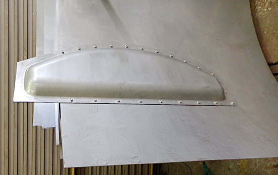
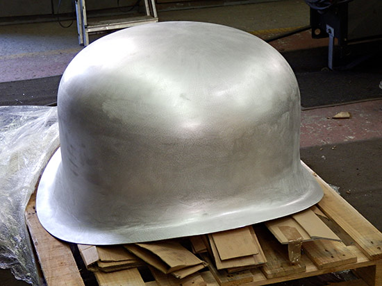
| The dome cover proved a problem to produce in steel, so we opted for Premier Group sheet metal to make it from Aluminium, and a few weeks ago it was delivered to us. |
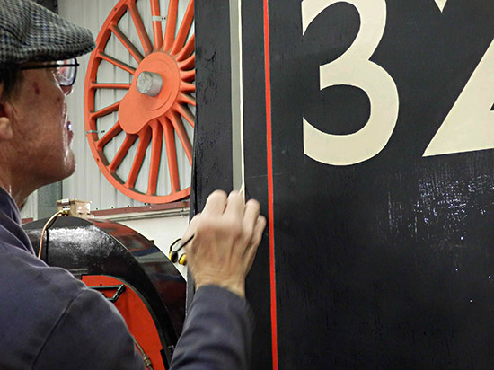
| A lot of people believe the lining, being so even, to be transfers or painted between strips of masking tape, but no, here is Tony putting on the fine straw-coloured line next to the wider grey one. |
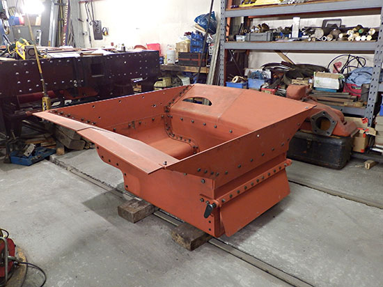
| Here we have the almost completed ashpan. We need to wait to weld it as the new health and safety regulations do not allow people to be present when welding is being carried out unless they, like the welder, have a filtered air supply helmet, or the shed is equipped with a proper filtered extractor. In Atlantic House the latter is not available, as the amount of welding that we need to do is insufficient to justify the considerable expense of the proper extraction equipment. |
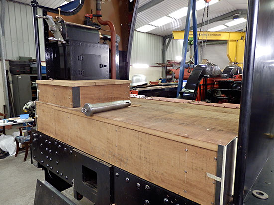
| The cab floor is now almost finished with the exception of fitting the final screws. We still need access to the area under the floor for pipes and for various reinforcing plates to support the rear of the hinges for the fall plate between the engine and tender. On the floor at the rear is the draw-bar pin. This is accessed through a hole in the cab floor that will be fitted with a recessed cover. |
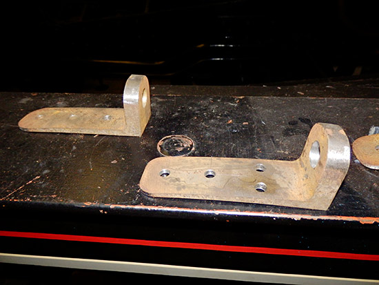
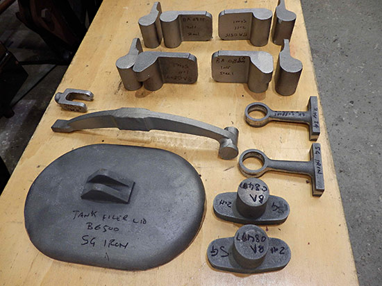
| Some castings received last week for the tank filler lid with its clamp bar and the forked retainer to hold the bar and hence the lid closed. To the right of the lid are castings that take the bottom of the handrail pillars. Above them are the support brackets for the injector valve spindle guide tubes and then the 8 castings required for the hinges for the cab doors. |
April 2019
|
Atlantic House – Open Weekend The annual Bluebell Atlantic Open Weekend gives the opportunity for supporters and visitors to see the latest progress with the construction of ‘Beachy Head’. Atlantic House at Sheffield Park will be open both days. There is an auction at 2.45pm on Sunday, with a large number of high quality LBSCR photos (13 lots with an average of 100 photos in each lot.) The albums are of grouped subjects rather than miscellaneous, e.g. locos classes C, C1, C2 and C3. We also have a replica King class numberplate, lamps etc. Viewing is from Saturday morning, and the team will accept commission bids if you’re unable to be there on the Sunday afternoon. |
The component sponsorship list has been updated.
February 2019
Fred Bailey updates us on work on the boiler and the tender.
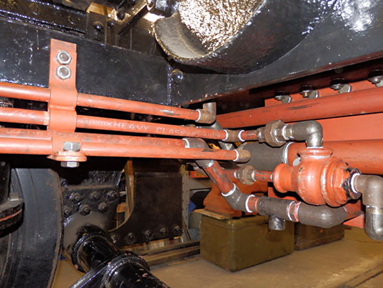
| Here is a picture of the pipework under the front end of the tender. To the right, painted black is the air brake cylinder. All the smaller pipes are part of the air brake system. The larger one at the very top is for steam heat to the train.Unseen here, the steam heat pipe is tucked up under the outside valance running down the left hand side of the tender, and the vacuum train pipe follows a similar route along the right hand side. |
| More pipework, basically as in the previous shot, but including one of the many support brackets. These are all individually made to fit in specific places where it is convenient to support the pipework. A lot of work – all completely forgotten about but vital to the security of the pipework systems. |
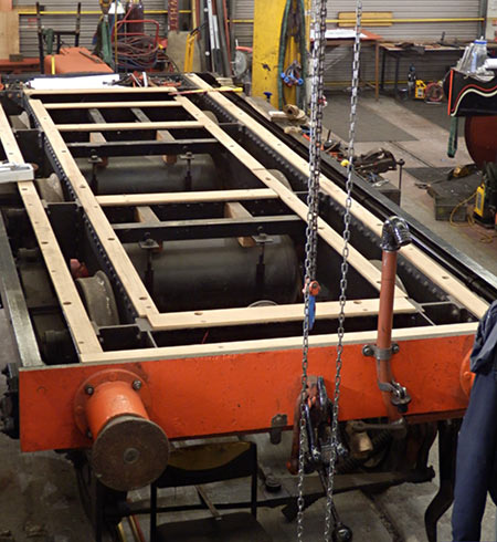
| Here is a view looking down the tender chassis which is now virtually complete, and has been fitted up with the wooden bearers upon which the tank itself sits.Quotations are awaited for the production of the actual tender tank. The main part of this will be a welded fabrication, but the detail work consisting of the coal rails, and half round beading is all riveted and will be carried out in Atlantic House by the normal Atlantic construction team.
Most “Brighton” tenders, like the tanks on their tank engines, are double skinned. This is basically a second tank that wraps around and is bolted to the inner actual tank. It has the advantage of hiding the quick crude riveting on the original tenders or of any rippling of our welded one. This feature may well have been of an advantage as an insulator for all the tanks fitted to locomotives that condensed their exhaust steam to be used as a warm feed to the boiler via a hot water injector or a Weir or similar boiler feed pump. |
| This shows the boiler outside with work progressing on the making up and fitting of the crinolines that support the outer boiler cleating sheets. The boiler requires a little further work before it is ready for its hydraulic test, but a change in the dating of boiler test certificates from the steam test date to the hydraulic test date required by our boiler inspector means that we wish to delay the hydraulic test in order to gain as much time in service from the test date as possible.To this end we are intending to fit the crinolines, smokebox etc. now rather than later. A further consideration is none of us (being older and of more experienced minds) wish to work inside a steel boiler covered in frost with a wind from the arctic blowing! |
| Carrying on from the above, here we have the smokebox as first fitted to the boiler, supported on our lifting frames (which were built to re-wheel the loco chassis whilst in our shed).A certain amount of adjustment was then done to get it aligned reasonably to the boiler after which the job of drilling through the holes for the fastenings can proceed. |
| With a recent spell of warmer weather we have started on this drilling job, and this shows our method using the usual air driven drill, supported and guided from the opposite fixing hole. A nice job if you like hot steel swarf up your sleeves or down your shirt front. |
Inside Atlantic House, the ashpan is under construction and a big pile of timber has arrived ready to start making the cab floor. With the tender tank not yet ordered we are working on a range of fronts until such time as the tender tank is delivered. At best this might be in July.

Older news updates
- Background and early progress
- September 2001: Repairs to tender chassis.
- More photos of the project (1999-2002).
- March 2002: Modification of front end of tender.
- November 2004: Loco Frames ordered.
- December 2004: Bogie frame components arrive – also Feb.2005 news report.
- 2005 – Loco main frames arrive – tender frames nearly completed – start of construction of the shed.
- 2006 – Loco driving wheel castings delivered – drilling of the main frames and hornguides – building of the shed completed.
- 2007 – Main locomotive frames erected.
- 2008 – Components for the cylinders and valve chest delivered – frames riveted – forged billets for connecting and coupling rods delivered.
- 2009 – First motion parts water-jet cut from forged blanks – bogie frames assembled.
- 2010 – Cylinders and valve chests fabricated, air brake cylinders completed, bogie and trailing wheelsets completed.
- 2011 – Coupling rods and axleboxes delivered, reverser mechanism completed, crossheads cast.
- 2012 – Valve and cylinder liners fitted – lifting and reversing arms and axlebox crowns delivered – castings for mudhole doors, regulator and whistle valves, reversing shaft clutch, blast-pipe cap, crosshead slippers, ‘J’ pipe and eight eccentric halves received – Bogie and trailing axle now support the frames – Valve chest and cylinders fitted to frames, covers fitted, and pressure tested.
- 2013 – Cylinders, valves, slidebars and crossheads completed – driving wheels completed – valve gear components delivered – lifting frames constructed.
- 2014 – Weigh (reversing) shaft and air-clutch fitted, axleboxes metalled, machined and fitted, wheel rotators constructed, eccentric rods, valve and reversing gear, pipework for brakes and steam heat completed, locomotive wheeled, cylinders clad and crossheads fitted.
- 2015 – Rolling Chassis completed with all motion erected. Running plates and splashers completed, along with cab sides and front.
- 2016 – Connecting and coupling rods fitted, valves set. Superheater header delivered. Revision of boiler internal pipework completed. Cab roof riveted together and fitted. Mud-hole patches welded into boiler. Flue tubes (with screw ends welded on) delivered.
- 2017 – Major progress on the boiler overhaul, and with the safety valves.
- 2018 – Boiler tubes fitted, tender made mobile, complex parts of the boiler cladding made.

Project funding
A fund raising appeal for the money required to complete the project was launched in 2000, and a combination of gifts made via the Bluebell Railway Trust, and standing orders set up to provide a steady income to the project have provided funding for the present work. However, more is still needed to complete the project, and the best way in which you can help is by setting up a small, regular, standing order to the Bluebell Railway Trust under Gift Aid, since this enables the Trust to reclaim the basic rate tax you have paid, and (if you are a higher rate tax-payer) enables you to reclaim some tax as well.
A combined Donation, GiftAid and Standing Order form is available as a pdf document.
For further details contact David Jones.
Photos © Fred Bailey, Neil Glaskin, Malcolm Place, David Jones, Melvyn Frohnsdorf, D G Welding, F. Wijenbergh, and S. Burdett (The Premier Group).
Last updated 15 August 2024 by Richard Salmon
