How our signalling works
- Signals, Signalling and the Bluebell
- Bell Codes
- Electric Train Staff Instruments
- Electric Train Key-Token Instruments
- The Walkers Train Describers
- The Signal Boxes
Signals, Signalling and the Bluebell
This article (slightly modified from the one which appeared in the Winter 1998 edition of Bluebell News) is not intended as an in-depth highly-technical review of signalling practices, more a source of general information about this complex subject and how it affects the Bluebell Railway.
In the earliest days of railways, trains were not really regulated at all – they were despatched at intervals with a minimum time allowed between them. As railways grew and technology improved, both the number and speed of trains increased, leading to inevitable mishaps. To try to regulate things better, Railway Policemen were employed and they were literally a form of human signal, policing the traffic on their line and endeavouring to keep the trains a safe distance apart. (They were, naturally, nick-named “Bobbies”, a name which was subsequently inherited by Signalmen and is still in use to this day). The human knack for misunderstanding and error soon led to the development of a form of mechanical signalling controlled from a central point, the signalbox.
Much improved as this system was, there were still plenty of opportunities for error, leading to many well-documented accidents, so that eventually Parliament had to intervene and formally regulate the various railway companies to make them safer. There have been many, many different Acts of Parliament covering all topics of safety but probably the most important was the Regulation of Railways Act of 1889 which made compulsory: block working (making it impossible for more than one train to occupy any one “block” of track), interlocking (making it impossible to set a conflicting route, or signal a route other than the one set), the locking of facing points and the continuous train brake. This meant a lot of work for some of the railways, such as the Cambrian, which had (through their dire financial conditions) been unable to make much effort to improve the safety of their lines. The LB&SCR was one railway at the forefront of railway safety, having had the misfortune of some spectacular accidents early in its life!
Large railways developed their own systems whilst smaller ones would purchase “off the shelf” from companies such as McKenzie & Holland, Saxby & Farmer or Westinghouse. But, different as their appearance might be, the basic functions were all the same. By and large you can divide signals into three categories, running signals which control trains along their route, shunting signals which control movements over short distances and information signals. Here are described the various types you can see along the route of the Bluebell:-
1. Running Signals.
These are the most well-known, and easily recognised even by people with no interest in railways. They fall into two categories, the Stop signal and the Caution signal.
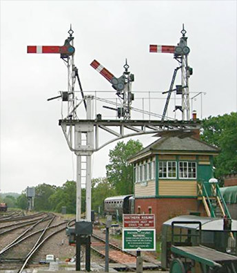
Fig.1 Stop Signals at the north of Horsted Keynes Station.
Stop signals are normally an arm with a red face and a white stripe on the front whilst the reverse is white with a black stripe. Fig.1 shows the Stop signals controlling the exit north from platforms 3 & 4 and 5 at Horsted Keynes, and the two First Advanced Starting signals by the bridge in the background. (Note the white-painted brickwork behind the signal arms, to help make them visible). Caution signals are usually “fish-tailed” and painted yellow with a black “>” stripe on the front and white with a black “< ” stripe on the reverse. When a signal’s arm is horizontal it is said to be “on” and when it is either raised or lowered, it is said to be “off”.
Their meanings are quite simple, when the Stop signal is “on” the train must stop and when it is “off” the section is clear all the way to the next Stop signal and the train may proceed whilst if a Caution (more commonly known as a Distant) signal is “on” it tells the driver they must be prepared to stop at the next Stop signal whilst when it is “off” (as in Fig.2, right, the Up Outer Distant Signal to the south of Horsted Keynes – Peter Edwards) it tells them the next Stop signal (or series of Stop signals, depending on the local arrangement) is also “off”. It therefore follows that a Driver may pass a Distant signal that is “on” but may never pass a Stop signal that is “on” unless specifically authorised to do so by the Signalman.
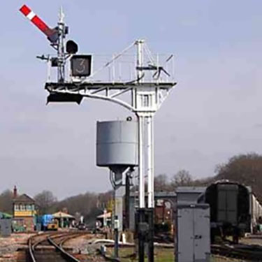
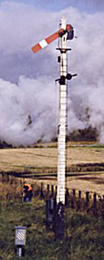
Fig.3 Left: The upper quadrant Inner Home signal controlling entrance to Horsted Keynes station from the south.
Photo: Chris Majer.
Fig.4 Right: The lower quadrant Advanced Starting signal at Sheffield Park that allows entry to the single line section.
In the early days most signals were lowered to the “off” position and are called lower-quadrant but there were some accidents caused by broken signal wires allowing the arm to fall when it shouldn’t which led many railways to adopt the raised arm, or upper-quadrant signal. (Note the different arrangement the two designs of signal have for the spectacle plates that show a coloured light after dark). Those that stayed with the lower-quadrant arm introduced a weight to counter the weight of the signal arm so that if the wire were to break the signal would remain at danger. Subsequently the counter-weight was introduced to upper-quadrant signals as well. A few railways had a rather complicated “somersault” arrangement whereby the signal arm would pivot, away from its post, through 90 degrees so that when “off” the arm was vertical. The Bluebell has examples of both lower quadrant signals as used by the LB&SCR and upper quadrant signals as used by the SR. Signalposts can carry more than one arm, the most common forms of multi-arm signal being those with a Stop arm at the top and a Distant arm below, and the bracket signal.
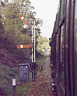 The bracket signal can carry two or more raised posts, arranged according to the route they control. The “main” route will always be controlled by the signal on the highest post so if a bracket signal controls a junction with a branch line or siding leading off to the left, then the main route will be controlled by the higher arm, usually mounted on a post directly above the supporting post below the bracket, whilst the line branching off will be controlled by the signal on a shorter arm, off-set to the left. (A bigger development of the bracket signal is the gantry signal, spanning several tracks, where the route controlled is identified by reading the signal arms from left to right, the importance of the route being reflected by the height of the signal arm. We do not have a gantry signal on the Bluebell). Where a single post carries two or more Stop arms, (as in Fig.5, left,the home signal just south of Kingscote station) then as you read the arms down the post from top to bottom they apply to the routes from left to right. In this photograph the road is set for the train to enter the “main” (one day to be the “up”) platform at Kingscote station.
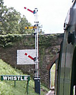 Another, more common, use of more than one arm on a signalpost is where there are both Home and a Distant signal arms. Fig.6, right, shows the down outer home for Horsted Keynes with, in addition, a repeater arm for the Home signal. These are used in situations where there is a problem sighting a signal, usually because the driver would not see it until almost at it, so the “main” arm is the higher one whilst the lower one is the repeating one, easily seen from the cab of a locomotive standing at the signal. The Caution signal beneath the Stop signal is permanently in the Caution position and is known as a Fixed Distant, though will be a working signal when the re-signalling of Horsted is complete. For night use the signals will display a green light when “off”, a red light for a Stop signal which is “on” or a yellow light for a Distant signal which is “on”. A Fixed Distant can, of course, only ever have a yellow light.
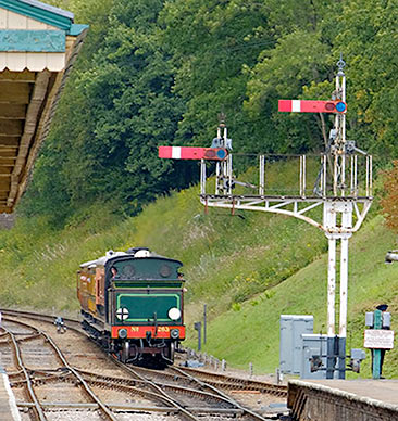
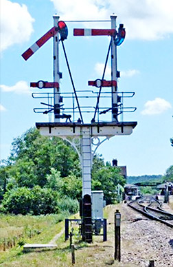 Fig.7, left. The bracket Starting signals at the north end of platform 3 at Horsted Keynes (photographed by Brian Lacey in September 2018). The righthand arm is on a taller doll as it refers to the main through route. The lefthand arm is lower as it refers to the route via the crossover to the loop line on the left.
Fig.8, right. The equal bracket, lower quadrant, Inner Home signals at the approach to Sheffield Park. Both lines are of equal status so both signals are the same height and mounted on posts set an equal distance from the supporting post. The lower arms are known as “calling-on signals” and permit movements past the signal when the platform line is occupied.
2. Shunting Signals.
These can take many forms and I don’t intend to detail them all. The calling on signals above are one example. Most of the various different types used on the Bluebell are illustrated.
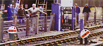
 The most common ones are rotating discs, (as in Fig.9, left, SR Westinghouse pattern disc signals at Sheffield Park. The one on the left is “on” whilst that on the right is “off”) either white with a red stripe or yellow with a black stripe, and arms which are a smaller version of the Stop signal arm, (as the two righthand arms in fig.10, right: Shunt arms for the Ardingly siding at Horsted Keynes, Chris Majer) sometimes with a letter, often with a circle attached to their face (as in fig.8 above).
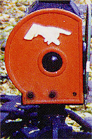
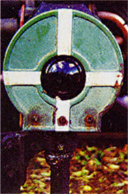 Figs. 11a, left, and 11b, right.
We have one gem that was used for many years at Sheffield Park, an original LB&SCR shunt signal which rotates horizontally, thereby showing two faces towards the Driver. Unfortunately this signal started to show its age has been retired but will be moved to the sidings at Kingscote where it will not get so much wear and tear.
The two aspects of the LB&SCR shunt signal that used to control the exit from the Newick siding at Sheffield Park. This signal was wearing out and has now been ‘retired’ to our museum.
When “on” there is a red aspect with a white hand pointing to the track it protects and when “off” a green aspect with a white cross.
The function of a shunting signal is simple, when it is “off” it permits the driver to pass, but unlike a running signal, only for as far as they can see the line to be clear. It does not necessarily give them permission to proceed as far as the next signal and must be prepared to stop at any time after passing the signal. If the signal is yellow with a black stripe, then it may be passed when “on” providing the movement is not in the direction controlled by the signal, which avoids the need for lots of shunt signals in sidings which can be safely operated by a shunter. At Horsted Keynes there was such a yellow and black shunt signal which controlled movement out of the down sidings, enabling movements to take place within the sidings whilst it was “on” providing they did not entail leaving the sidings. This has been temporarily replaced with a colour light Position Light signal and will be replaced by a white disc with a red stripe, which must be obeyed for all movements.
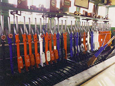
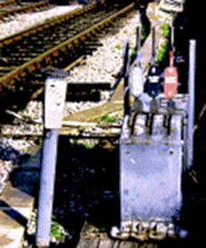
The points and signals are operated from lever frames. Most of these levers are in the signalboxes but some can be outside, in a ground frame. Fig.12 shows the frame in Horsted Keynes signalbox and fig.13 the ground frame that was used at the north of platform five at Horsted. Red levers control the Stop signals, the yellow one at the far end the Distant signal, black levers operate the points and blue ones lock the points. The brown and blue lever locks or unlocks the ground frame. The brown and white ones are used to close the box with points locked and signals “off” permitting movement of trains on one line only when signalbox is un-manned. The white levers are spare levers. Since 1998 all levers have been dis-connected as a result of the work now in progress on the permanent way and signalling. These will all be connected once more when the re-signalling of Horsted is complete.
3. Information Signals.
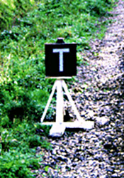
This category covers many “signals” from signs advising drivers of speed restrictions to signs advising them of a change of gradient to signs instructing them to sound their whistle to Stop Boards that require the driver to stop his train and call the signalbox to obtain the signalman’s permission to proceed. Many of them may be seen in the following illustrations.
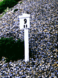
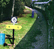
Fig.14, left. A railway milepost. Distances on the Bluebell are measured in miles and quarter miles from Culver Junction.
Fig.15, right. The sign giving advance warning that there is a speed restriction ahead.
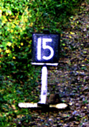
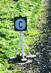
Fig.16a, left and Fig.16b, right. Two alternative signs advising the driver of the commencement of a speed restriction.
- Signals, Signalling and the Bluebell
- Bell Codes
- Electric Train Staff Instruments
- Electric Train Key-Token Instruments
- The Walkers Train Describers
- The Signal Boxes
Text and non-attributed Photographs Copyright © Peter Richards.
Page last updated 21 March 2013 by Peter Richards
and 26 February 2023 by Richard Salmon.
